Datasheet
G1QX "GLIDE" DIN-rail 4-20mA Analog Signal Loop Converter, Indicator and Communicator
Introduction
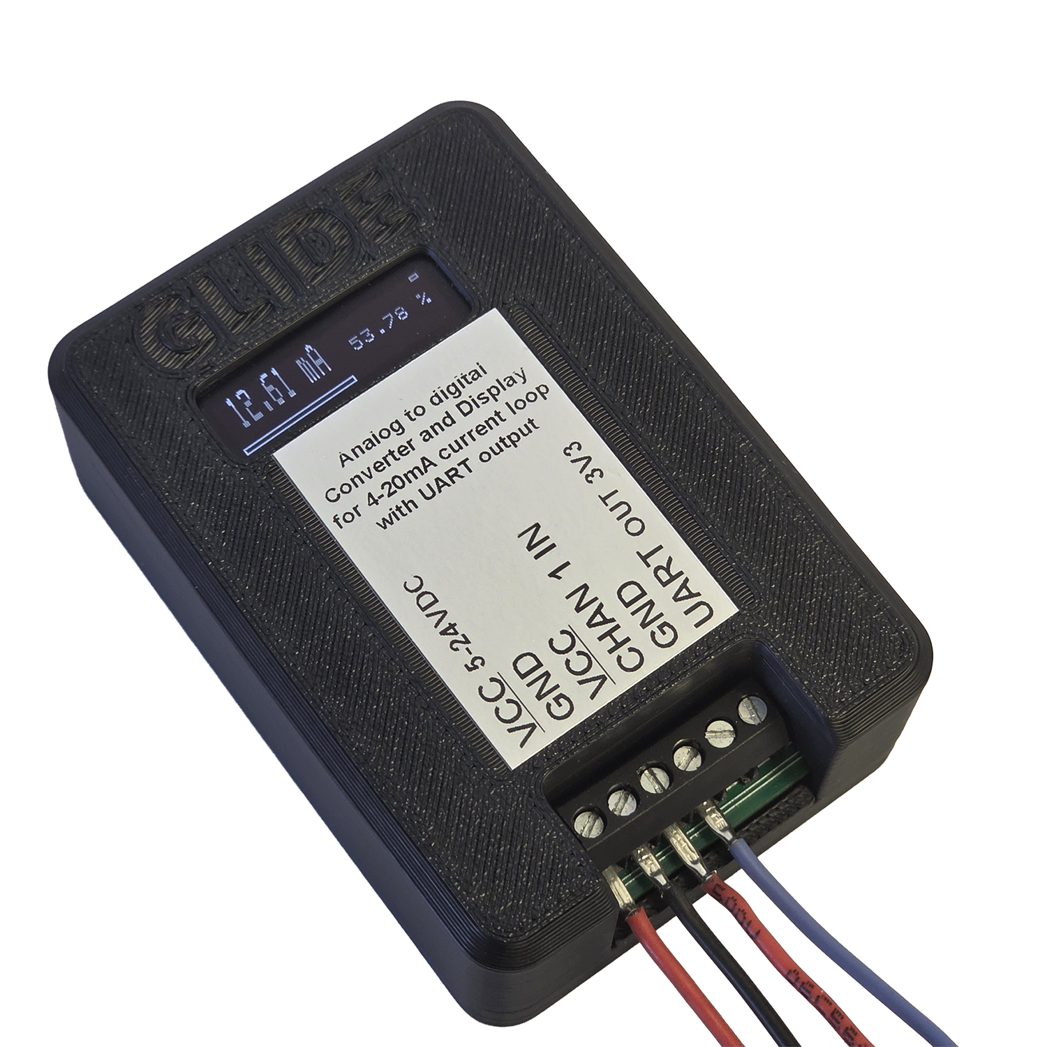
"GLIDE" unit is used to show and digitize current output of any 4-20mA sensor (current loop). Display and digital UART output present the value of the electrical current. In addition, 4-20mA scale is mapped to percentages (0-100% mapped to 4-20mA output). A compact OLED display is used.
Unit provides serial interface to transfer the converted values over 3V3 TTL signalled UART interface to SCADA or other control system.
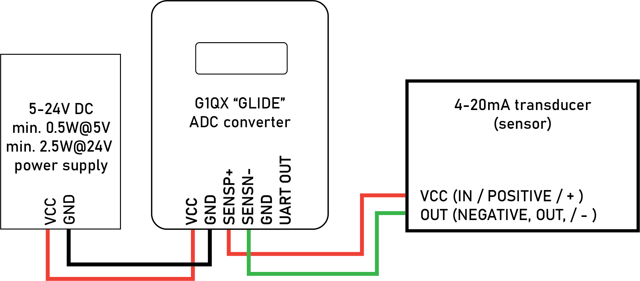
The device must be powered from a power source of 5-24V DC using the dedicated input power pins and also provides this input voltage to sensor through LOOP+ pin.
Application
As a permanent display of the current loop sensor in distribution cabinets and as a compact low-cost ADC for simple or more complex automation installations. Simplicity of UART interface protocol makes this unit suitable for Industrial-IoT applications.
Technical parameters
| Type of measurement | electrical current |
| Designed measurement range | 4-20mA |
| Combined measurement precision | 0.4% standard; see order table below for options (accounts for non-linearity of measurement, hysteresis and repeatability) |
| Long-term drift | 0.01% per year |
| Recommended calibration frequency | once every two years |
| Power supply | 5V - 24V DC (min. 2.5W@24V) |
| Environmental conditions | -20C to +40C, 90% relative humidity |
| Communication | UART (3.3V TTL) |
| IP protection grade according to (IEC 60 529) EN 60 529 | IP 50 |
Notes on calibration
Each unit is individually calibrated against high-precision laboratory-grade ammeter at four points along the 4-20mA scale using quadratic polynomial compensation function. Calibrations are performed under laboratory reference environmental conditions of (23 ± 5) °C and relative humidity (50 ± 20) %, in accordance with recommendations of the International Organization of Legal Metrology (OIML)(see www.oiml.org).
Order code table
| Output types (E) | |
| E0 | display + TTL UART TX only at 1Hz |
| E1 | display + RS485 MODBUS max. 1Hz |
| EX | special - on request |
| Combined measurement precision (P) | |
| P0 | 0.4% |
| P1 | 0.25% |
| PX | special - on request |
| Number of measurement channels (W) | |
| W0 | 1 |
| W1 | 2 |
| W2 | 3 |
| W3 | 4 |
| WX | special - on request |
Installation
Physical installation of the unit
Unit is designed to be installed on standard DIN-rail. Attach the top part of the DIN rail clip first, then snap in the bottom part of the unit into place.
Screw terminals on the unit hold individual wires of 28/18 AWG (0.08/0.75 mm^2).
Wiring diagram
Communication interface (UART)
The UART interface is an output only interface - it does NOT accept commands so its possible only to use the TX line from the GLIDE to RX line on receiving side. RX line on GLIDE unit is not available.
The 3V3 TTL signal is referenced to GND pin.
UART protocol is set to 9600 baud, 8N1 and cannot be changed.
For description og the UART protocol please consult G1QX manual available here: g1qx-manual.
Additional support
For support please contact manufacturer directly via info@quorumprecision.com