Datasheet
H1QP Pressure Sensor Datasheet
Overview
Digital pressure transducer H1QP is a pressure sensor, which is primarily used to measure pressure in distribution pipes of gases with analog or digital output interfaces.
Application
Pressure manometer H1QP is designed for precision measurement of overpressure, vacuum (negative gauge), or absolute pressure of gases or liquids inside distribution piping or containers. The main measurement body is made from stainless steel, so any medium which does not chemically react with stainless steel type DIN 1.4301, also known as AISI 304 also known as X5CrNi18 10, can be measured.
Technology
In manometer, the pressure the medium creates pushes on the mechanical membrane and changes electrical properties of the output signal, which is then electronically amplified and converted to digital numerical form. Next, this digital information is presented to the user, for example, as an analog signal (4-20mA output) or over digital interface over, for example, RS485 or UART (where usually MODBUS is used as a communication protocol).
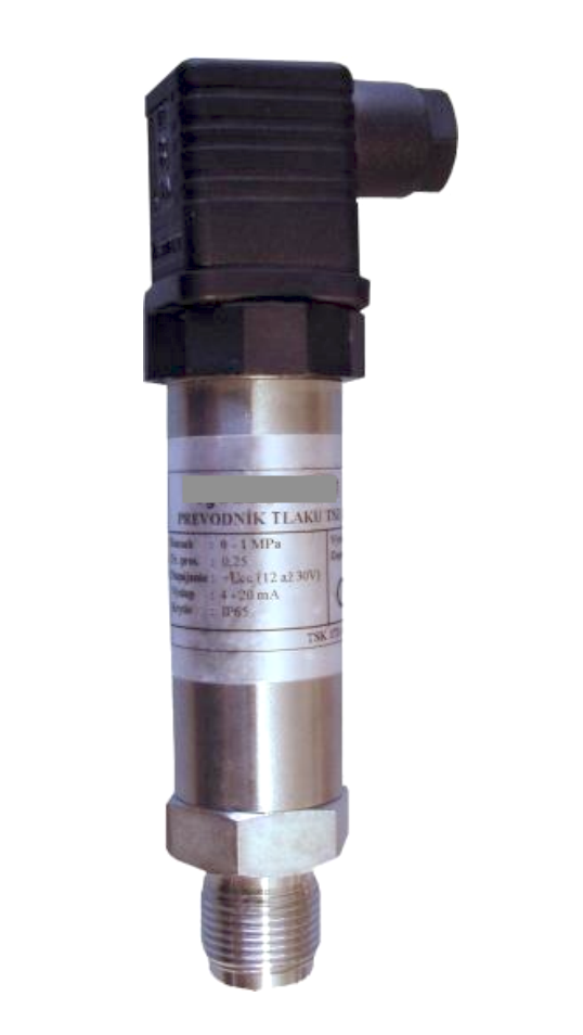
Mechanical information
The transducer is enclosed in a robust stainless steel enclosure.
Technical parameters
| Type of measurement | overpressure, vacuum (negative gauge), or absolute pressure |
| Maximum measurement range | 0 - 60MPa |
| Temperature of measured medium | min. -40°C, max. +125°C |
| Measurement precision | 0,1% of measured range for pressures more or equal to 25kPa 0,25% of measured range for all pressure ranges this combined precision accounts for non-linearity of measurement, hysteresis and repeatability |
| Additional measurement error due to ambient temperature | less than 0,03 %/10°C in the range of 0 to +60°C less than 0,03 %/10°C in the range of -20 to +60°C |
| Long-term precision stability | additional error of less than 0,15% of range per year |
| Recommended calibration frequency | once every two years |
| Power supply | 3.3V DC or 5V DC or 12V DC supply |
| Physical communication interface | RS485 or UART or 4-20mA analog output |
| Process attachment | M20x1,5; G½; G¼; other - see ordering table below |
| Material of process attachment | DIN 1.4301 (AISI 304 / X5CrNi18 10) stainless steel |
| Isolation resistance at 500V | RIZ > 2 M Ohm |
| IP protection grade according to (IEC 60 529) EN 60 529 | IP 68 |
Weight and dimensions
Weight:
Dimensions in [mm]
Software
Data logger software for Linux, Mac and Windows is available on https://github.com/quorumprecision/meret_integration_software/tree/master/bap2_logger
Contact us for more integration options on info@moirelabs.com
Markings
Information included on the label:
- Manufacturer
- Unit order code
- Measurement range and measurement precision
- Serial number
- IP rating
How to order
Order shall contain the following information:
- Date and internal number of the order
- Name and address (including VAT number where appropriate)
- Order number assembled from order tables including number of units and requested delivery date
- Type of delivery
- Optional extras to include (for example high pressure shock damping filter)
Order codes table
Danger
For all pressures up to 40 MPa: Short-term overload pressure of the sensors is double of its measurement range. Burst pressure is tripple of the measurement range. Pressures above overload pressure may cause sensor damage. Pressures above burst pressure may pose health risk to operators and equipment.
For all pressures above 40 MPa: Short-term overload pressure of the sensors is 1.5-times its measurement range. Burst pressure is double of the measurement range. Pressures above overload pressure may cause sensor damage. Pressures above burst pressure may pose health risk to operators and equipment.
Example: 0-60 MPa sensors max measurement range: 0-60 MPa. Short-term overload pressure: 90 MPa. Burst pressure: 120 MPa.
| Measurement range (M) | |
| M0 | 0 - 2.5 kPa |
| M1 | 0 - 4 kPa |
| M2 | 0 - 6 kPa |
| M3 | 0 - 10 kPa |
| M4 | 0 - 16 kPa |
| M5 | 0 - 25 kPa |
| M6 | 0 - 40 kPa |
| M7 | 0 - 60 kPa |
| M8 | 0 - 100 kPa |
| M9 | 0 - 160 kPa |
| M10 | 0 - 250 kPa |
| M11 | 0 - 400 kPa |
| M12 | 0 - 600 kPa |
| M13 | 0 - 1 MPa |
| M14 | 0 - 1.6 MPa |
| M15 | 0 - 2 MPa |
| M16 | 0 - 2.5 MPa |
| M17 | 0 - 2.8 MPa |
| M18 | 0 - 4 MPa |
| M19 | 0 - 6 MPa |
| M20 | 0 - 10 MPa |
| M21 | 0 - 16 MPa |
| M22 | 0 - 25 MPa |
| M23 | 0 - 40 MPa |
| M24 | 0 - 60 MPa |
| M25 | 80 - 520 kPa |
| M26 | -1 to 0 kPa |
| M27 | -100 - 0 kPa |
| M28 | -100 - 100 kPa |
| M29 | barometric pressure |
| MX | special - on request |
| Communication interface (R) | |
| R0 | TTL / UART with MODBUS |
| R1 | RS-485 (TIA-485(-A) / EIA-485) with MODBUS |
| R2 | 4-20mA analog output |
| R3 | USB 1.x (Win, Linux, MacOS drivers) with MODBUS |
| RX | special - on request |
| Connector type (A) | |
| A0 | Valve connector DIN 43650-A (IP65) |
| A1 | Hirschmann CA3GS (IP67) |
| A2 | Hirschmann CA6GS (IP67) |
| A3 | Sealed cable 5m long (IP68) |
| A4 | Sealed cable 10m long (IP68) |
| A5 | Sealed cable 20m long (IP68) |
| A6 | Sealed cable 40m long (IP68) |
| A7 | Sealed cable 80m long (IP68) |
| AX | special - on request |
| Power supply type (C) | |
| C0 | 3.3V DC (1W) |
| C1 | 5V DC (1W) |
| C2 | 12V DC (1W) |
| CX | special - on request |
| Measurement precision (P) | |
| P0 | 0.1% |
| P1 | 0.25% |
| P2 | 0.4% |
| P3 | 0.5% |
| PX | special - on request |
| Measured pressure type (T) | |
| T0 | absolute pressure against vacuum |
| T1 | underpressure / overpressure against atmospheric pressure |
| TX | special - on request |
| Max ambient temperature range (W) | |
| W0 | -20°C to +60°C |
| W1 | 0°C to +60°C |
| WX | special - on request |
| Mounting thread (H) | |
| H0 | M20x1.5 (External) |
| H1 | G1/2 (External) (BSP-BSPP, ISO 228, DIN 259, BS2776, JIS B0202 (PS)) |
| H2 | G1/4 (External) (BSP-BSPP, ISO 228, DIN 259, BS2776, JIS B0202 (PS)) |
| H3 | NPT 1/2 (External) |
| H4 | clamp type (no threading) |
| H5 | wall installation bracket |
| H6 | NPT 1/4 (External) |
| HX | special - on request |
| Type of measurement nozzle (N) | |
| N0 | standard (with raised nozzle) (EN 837) |
| N1 | clamp (DIN 32676) size 32 (ID of pipe) - material: DIN 1.4301 (US/BS 304) |
| N2 | barometric pressure measurement attachment |
| N3 | ISO KF25 |
| NX | special - on request |
Packaging
Sensors are packed individually into padded cartons.
The packaging includes all information required for proper use and servicing of the equipment.
Physical installation
The manometer is screwed on to the measurement place with appropriate spanner (24mm). The inner thread type on the measurement place and on the manometer must match! Tightness of the connection is ensured by appropriate gasket - not part of the delivery. The body of the manometer must not be used for tightening of the manometer onto the measured place. Always use spanner and dedicated mounting nut.
Wiring information
Hirschmann CA6GS (7 male pins) connector (A2)
Mating connector: Hirschmann CA6LD (7 female pins)
TTL / UART (R0)
| Pin number | Function | Notes |
|---|---|---|
| 1 | VCC | power supply to sensor |
| 2 | GND | |
| 3 | UART TX (sensor data out) | |
| 4 | UART RX (sensor data in) | |
| 5 | not connected | |
| 6 | not connected | |
| 7 | VCC | pin 7 is shorted to pin 1 (VCC) - you can use this pin to power upstream device or simply indicate to the upstream device that physical connection was established |
RS485 (R1)
| Pin number | Function | Notes |
|---|---|---|
| 1 | VCC | power supply to sensor |
| 2 | GND | |
| 3 | RS485: A | |
| 4 | RS485: B | |
| 5 | not connected | |
| 6 | WAKEUP | Pulling low (to GND) wakes up the sensor for communication. Permanently wire to GND to disable sleep. |
| 7 | not connected |
Contacts
For support please contact your distributor or manufacturer directly via info@moirelabs.com