Manual
G1QX "GLIDE" DIN-rail 4-20mA Analog Signal Loop Converter, Indicator and Communicator
Introduction
"GLIDE" unit is used to show and digitize current output of any 4-20mA sensor (current loop). Display and digital output present the value of the electrical current. In addition 4-20mA scale is mapped to percentages (0-100% mapped to 4-20mA output). A compact OLED display is used.
Some units also provide serial interface to transfer the converted values over 3V3 TTL signalled UART interface to SCADA or other control system.
The device must be powered from a power source of 5-24V DC using the dedicated input power pins.
Application
As a permanent display of the current loop sensor in distribution cabinets and as a compact low-cost ADC for simple automation installations.
Installation
Connections / pins description
| Pin Name | Description |
|---|---|
| VCC | Pin providing power to the GLIDE unit (5-24V DC) |
| GND | Use this pin to connect negative rail of the power suply to the unit |
| LOOP+ | Pin that can be used to provide power to the 4-20mA sensor - this pin is tied to the VCC pin and provides the same power characteristics that are provided directly to the VCC pin. If different power source for the sensor is used please make sure the grounds of both power supplies are common. |
| LOOP- | Measurement pin of the 4-20mA loop - this pin is connected to GND over shunt (burden) resistor - connect the return path of the sensor to this pin. |
| GND | Concenience pin to use with the UART OUT pin. |
| UART OUT | UART TX pin - ADC data are available on this pin at 1Hz cadence. See Communication interface (UART) section for packet format information. |
Physical installation of the unit
Unit is designed to be installed on standard DIN-rail. Attach the top part of the DIM rail clip first, then snap in the bottom part of the unit.
Screw terminal on the unit holds individual wires of cross-section.
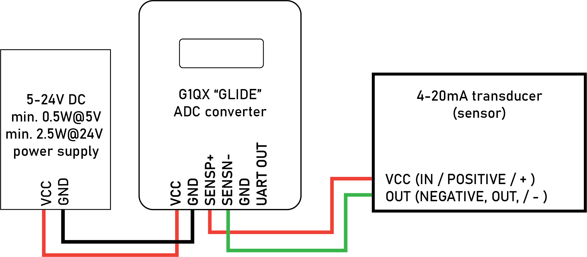
Wiring diagram
Communication interface (UART)
The UART interface is an output only interface - it does NOT accept commands so its possible only to use the TX line from the GLIDE to RX line on receiving side and RX line on GLIDE shall be not connected.
The 3V3 TTL signal is referenced to GND pin.
UART protocol is set to 9600 baud, 8N1.
Format of the output message (example in hex): 0x01 0x7D 0xEE 0x47 0x41 0xF3 "pause"
Where: 0x01 is a static header byte and 0x7DEE4741 is approx. 12.4957 miliamperes represented in a C-type 32 bit float type in "DCBA" little endian format. And 0xF3 represents checksum of the measurement bytes as checksum 8 - modulo 256. "pause" is about 900ms, which means, that always at least one measurement is sent every second (>1 Hz).
Support
For additional support please contact manufacturer directly via info@quorumprecision.com