G1QP "GLIDE": DIN-rail mountable 4-20mA Analog Signal Loop Converter, Indicator and Communicator
Manufacturer: Quorum Precision, Slovakia, EU; info@quorumprecision.com; https://www.quorumprecision.com/


| Power supply (VCC) | 5-24V DC, min. 2.5W@24V |
| Operating temperature | -20°C to +60°C, max. 95% non-condensing relative humidity |
| Measurement range and units | 4-20mA DC |
| Combined precision | 0.4% of the measurement range + 0.01% per year long-term drift |
| Device order code | G1QX-P0-W0-E0 |
| IP rating | IP50 |
| Wire gauge min/max | 28/18 AWG (0.08/0.75 mm^2) |
| UART config | 9600 baud, 8N1 |
Note
- Handle with care.
- Store at 10°C to 30°C and 20 to 80% relative, non-condensing, humidity.
- Please recycle at the end of life.
This product is not a toy. This device is an adjusted, calibrated measurement instrument.
Quick start guide on this page is not a substitute for the full manual.
| CE declaration of conformity, Spec Sheet and Manual are available on https://docs.quorumprecision.com/ or use QR code: |  |
Danger
- Measurement pin NOT isolated from power supply.
- The unit has NO reverse polarity protection.
Read Spec Sheet and Manual before powering up!
Package content: 1x This product sheet; 1x G1QP unit; 1x DIN-rail mounting attachment; 2x screws to mount DIN-rail attachment to the unit from back side
Warning
The unit can only measure the current on the LOW SIDE of the current loop with the loop and the unit sharing the same ground reference! Failing to do so may result in inaccurate measurements or damage to the device.
Installing the unit and connecting 4-20mA signal loop in two-wire configuration
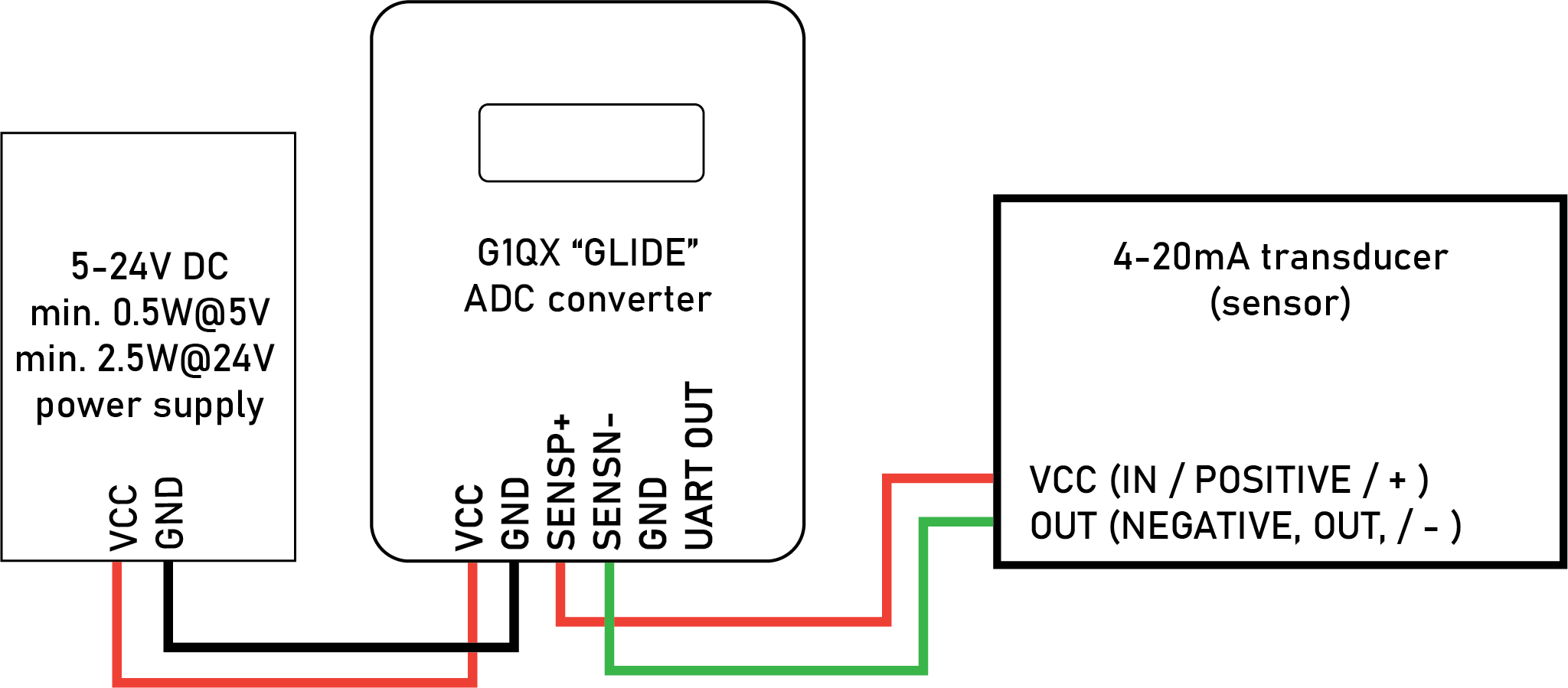
- Mount the DIN-rail attachment to the back of the unit using the provided screws and mount the unit to a DIN-rail.
- Connect the positive 4-20mA signal loop to the power pin marked "SENSP+" - this pin is tied to VCC pin.
- Connect the negative 4-20mA signal loop to the pin marked "SENSN-".
- Connect the negative power supply to the power input pin marked "GND".
- Connect the positive power supply to the power input pin marked "VCC".
The unit will now power up and start measuring the current on the channel 1 input pin. Observe the measurement on the display. The display will show the measured current in mA and the measurement as a percentage of the full scale (4-20mA = 0-100%).
Optional: Connect a 3.3V RX UART serial interface to the output UART pin (marked "UART OUT"). Don't forget to connect GND too. See Manual for packet format. End of document, please save this document for future reference.